System Noise Temperature In Satellite Communication

Cascaded noise temperature is done just like with noise figure.
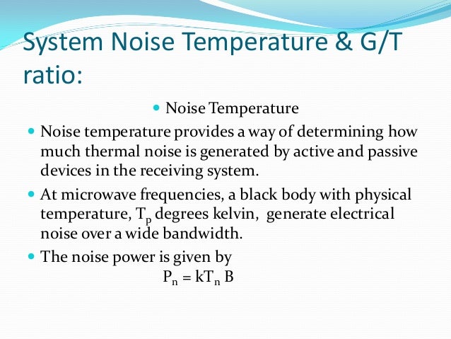
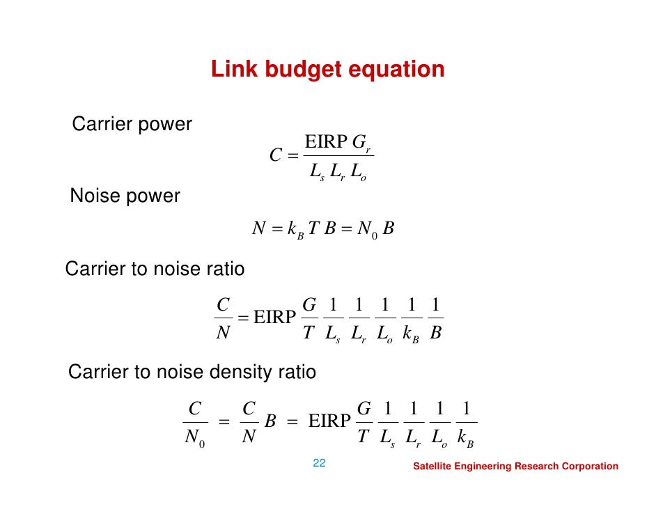
System noise temperature in satellite communication. Combining eqns 6 7 16 and 6 7 17 the system noise temperature can be calculated yielding. Where t s is the system temperature b is the if bandwidth and g if is the gain of the if amplifier system. Noise figure nf 10 log noise factor db. The noise figure can also be seen as the decrease in signal to noise ratio snr caused by passing a signal through a system if the original signal had a noise temperature of 290 k.
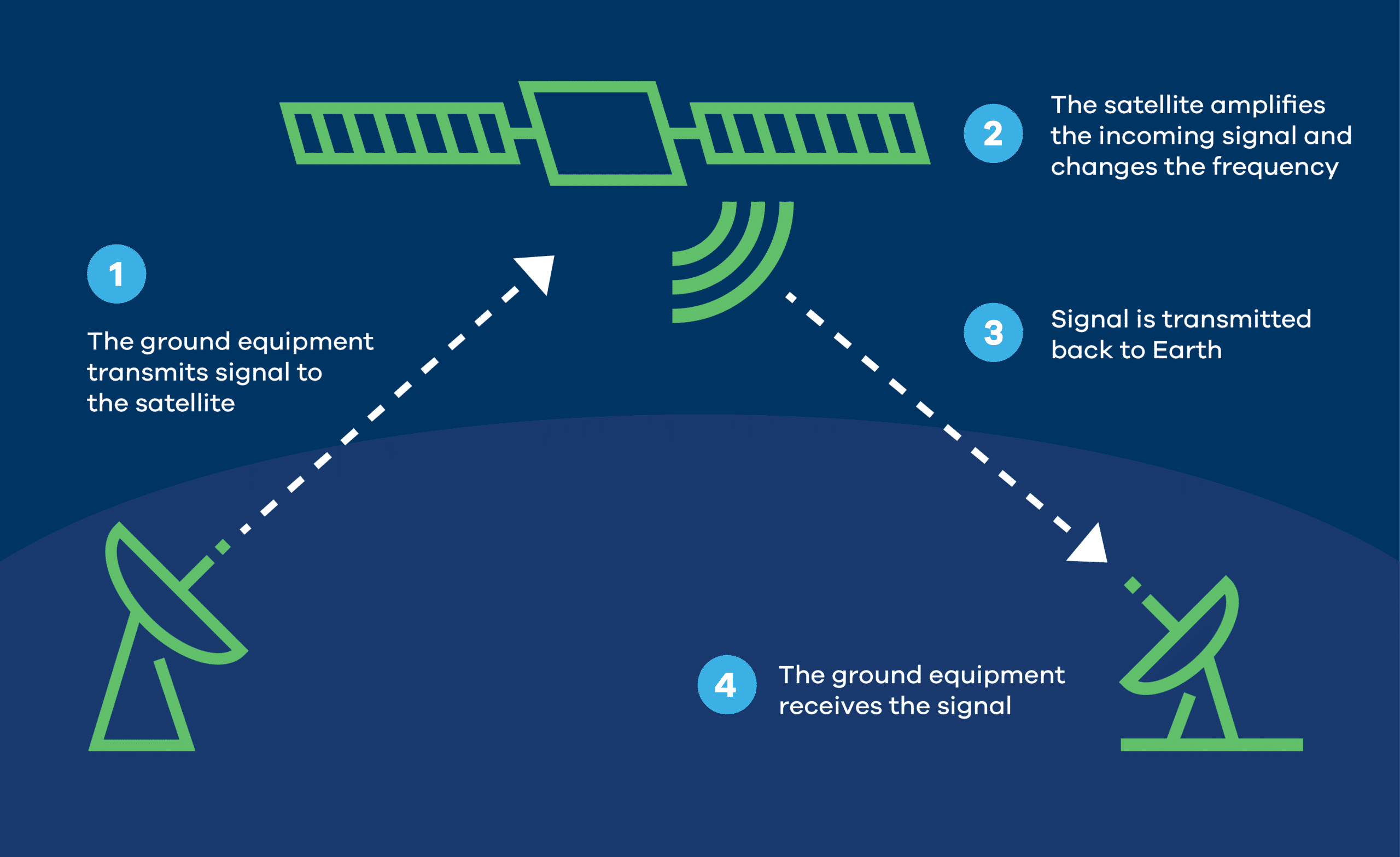
What do you mean by system noise temperature. 21 02 2006 3 satellite communications systems exist because earth is a sphere. This is a common way of expressing the noise contributed by a radio frequency amplifier regardless of the amplifier s gain. When using calculators and spreadsheets make sure that base 10 is selected.
Mumbai university extc sem 8 satellite communication and networks 8 1k views. Voice communications video radio transmission navigation gps remote sensing maps weather. If you begin with a system at room temperature 290 k and add a component at the input that itself has a noise temperature of 290 k the doubling of noise power increases the overall noise figure by 3 db 2 290 290 290. Noise temperature noise figure nf and noise factor f the basic formulae are.
Note that log must be to base 10. Satellite communication system noise temperature satellite link design ajal a j 03 07 14 assistant professor mob. Universal engineering college thrissur 680123 department of ece ec09 l05. System noise temperature satellite link design 1.
Calculate system noise temperature of a satellite having noise temperature 25 k increase in antenna noise due to rain 0 k lna noise temperature 50 k. How does it affect c n ratio and g i ratio calculate c n ratio in db hz given that b 36mhz calculate c n in db. Antenna gain to noise temperature g t is a figure of merit in the characterization of antenna performance where g is the antenna gain in decibels at the receive frequency and t is the equivalent noise temperature of the receiving system in kelvins the receiving system noise temperature is the summation of the antenna noise temperature and the rf chain noise temperature from the antenna. In the above p n h and p n c are the system output power when the input is terminated with a load at temperature t h t c.
A 6 db increase is a 4x increase in noise power 4 290 290 870. Otoshi1 with the advent of cryogenically cooled front end assemblies it has become the practice to define antenna system noise temperature at the horn aperture rather than at the low noise amplifier lna input port. Dec 2012 may 2014. System noise temperature antenna noise temperature increase in antenna noise due to rain lna noise temperature 25 0 50 75.
Noise temperature t 290 10 noise figure 10 1 k.


